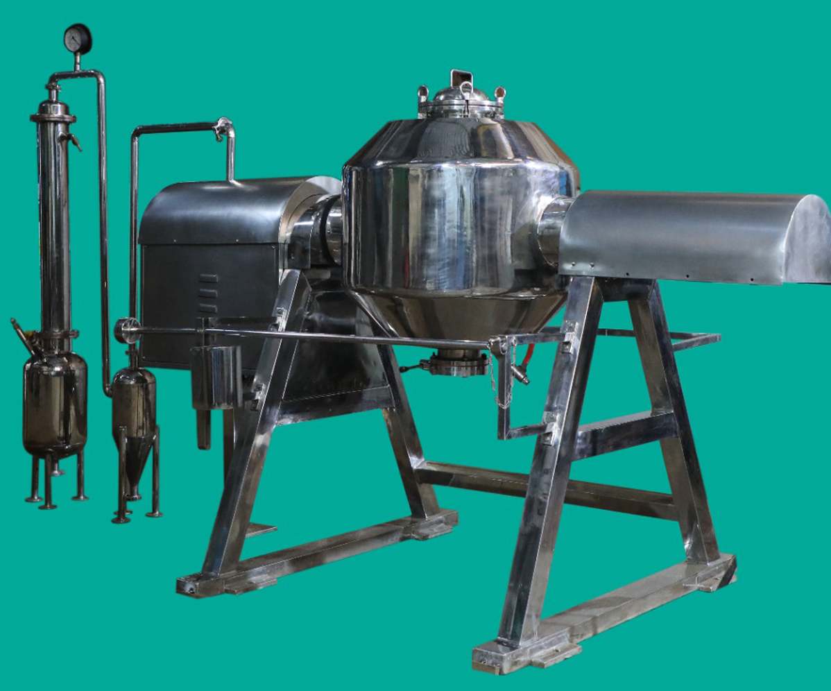
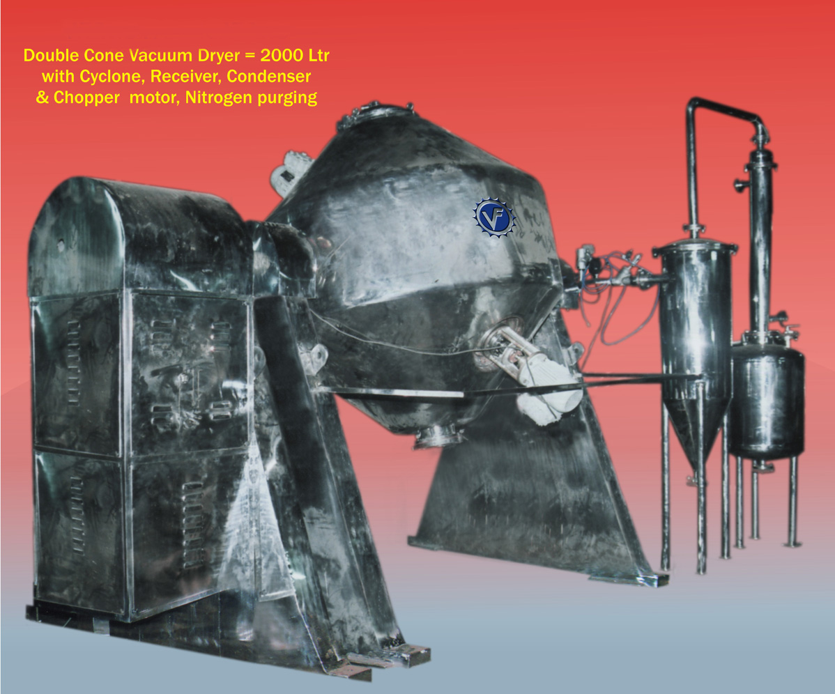
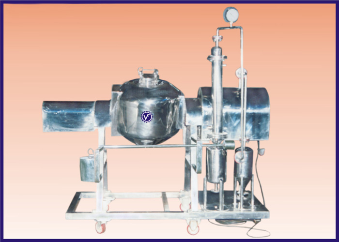
INTRODUCTION & WORKING PRINCIPLE OF THE DRIER.
In this equipment drying takes place at even low temperature and under vacuum. That is why, it is used economically and effectively for drying pharmaceuticals, temperature sensitive or easily oxidizable materials, when the solvent is present in the material, its easy recovery is possible. Drying takes place when the blender isolated & heated from outside the jacket and Vacuum is applied in the internals.
All drying operations are based on the principle that water or other volatile material moves from a zone of high vapour pressure to a zone of lower pressure. This is accomplished by warming the material to be dried to raise the vapour pressure of the absorbed or free liquid, by decreasing the vapour pressure of the gas by vacuum, or by sweeping it away with an air current. Thus the essential conditions for effective drying are:
EFFICIENT AND UNIFORM HEAT TRANSFER THROUGHOUT THE BATCH AND RAPID REMOVAL OF THE VAPOUR.
Shell
Consists of SS cylindrical central portion and top and bottom conical frustum. The shell is provided with a circular opening at one end for cleaning / discharge and a circular opening for charging/ discharge at the other end. The shell is welded with the hollow driving shafts, which are mounted with plummer blocks at the both ends.
The complete body is jacketted which is suitable for steam / hot water system for heating the material inside the dryer. Both steam / hot water for heating and vacuum systems are provided through the hollow driving shafts. Both the steam and vacuum system inlets are provided with suitable gland packing to suit the material to be dried. Vacuum is facilitated through a filter assembly, which, remains in upright conditions while the dryer is rotating to avoid any carry over of the material through a vacuum system.
Charging / Discharge
The smaller circular opening is provided with a butterfly valve to facilitate discharging of the dryer. The valve is operated by a lever arrangement designed to avoid accidental opening. A bigger cylindrical opening at the other end is provided with a circular lid with fixing gasket and handle and eye bolts for clamping. This opening is for cleaning the inside of the dryer and at times can be used for charging. An additional quick open dead plate is provided at the outer end of the butterfly valve to minimise vacuum leakage and additional safety.
Baffle
A suitable designed baffle is provided on a central shaft inside the dryer.
Drive
Drive mechanism consists of suitable electric motor, 3 phase 440 V 50 cycles 1440 RPM TEFC motor connected with suitable gear box through a belt drive. The gear box in turn connected to the driving hollow shaft through spur and pinion gears to give final RPM as required.
Mounting
The hollow driving / drivers shafts of the shell are mounted on suitable plummer block and the entire assembly along with drive is mounted on a rigid A shaped frame. Motor is mounted on an adjustment. The gear box is mounted on a rigid frame and is connected to drive shaft through spur gears. Entire assembly is well protected by a cover with hinged door for easy maintenance.
Safety Arrangement.
SS pipe railing is provided with limit switch arrangement to prevent unit from starting when the operator is working on the machine and when the railing is not in closed position. Rear fixed railing for additional safety is also provided.
Control Panel
Unit provided with control panel with starter and push button to actuate the drive and for INCHING OPERATION. Ample overload protection is provided by the MCB and the relay wires coming out of the connection are numbered for easy recognition.
Alternatively a hand cranking arrangement is also provided for bringing the unit to desired position during charging / discharging. IMPORTANT : CRANKING LEVER MUST BE DISENGAGED AND KEPT ASIDE TO AVOID INJURY DURING NORMAL RUNNING.